October 23, 2018
Cisco Releases Software-Defined Access v.1.2
The newest version of this solution offers some great enhancements for organizations.

Cisco recently released a new major update to its Software-Defined Access solution; the release notes detail what’s new. In this post, I assume you are already familiar with the SD-Access solution and instead focus on a few of the enhancements I think are most exciting.
Distributed Campus
One of the major missing pieces from SD-Access up until now has been the ability to connect multiple fabrics. Extending the security between the fabrics was clunky, requiring Security Group Tag Exchange Protocol (SXP) on non-fabric points in the network to enforce based on TrustSec tags, not to mention IP to Security Group Tag (SGT) mappings and other complexities.
With Distributed Campus, Cisco has introduced the ability to connect discrete fabrics together and extend segmentation and policy between them.
Note: This feature is meant only to connect fabrics in the same metro area that are joined via some type of metro connection (VPLS, Dark Fiber, etc.) that supports jumbo frames. An example would include connecting hospitals or schools in the same city. This feature is not meant to connect a fabric across a geographically distributed WAN.
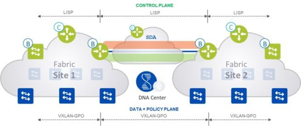
Distributed Campus adds another layer to the control plane with the Transit Controller. The Transit Controller’s job is to learn which prefixes live at which fabric and, via Locator/ID Separation Protocol (LISP), help direct the traffic between the sites. This Transit Controller can be a dedicated router at one of your SD-Access-enabled sites or can co-reside on one of your existing controllers. The local controller will have /32 routes for all the hosts at that site, whereas the Transit Controller will only have summary routes for the prefixes that live at each site. You will want to ensure you have architected the solution to properly support the scale of your environment.

Figure 1: Overview of Transit Site Feature — Courtesy of Cisco
When it comes to the data plane, Distributed Fabric maintains end-to-end virtual extensible LAN (VXLAN) encapsulation, so policy and segmentation can be applied between fabrics. The following is a packet walk:
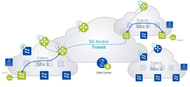
- Edge node in Site 1 sends a map request to control plane node in Site 1 for the IP of host 2 in Site 3.
- Control node in Site 1 sends a map reply informing the edge node in Site 1 to send the traffic to the local border node in Site 1.
- The traffic is sent from the edge node in Site 1 to the border node in Site 1.
- The border in Site 1, after receiving the traffic, will query the transit control plane node for the host information. This is made possible based on a dynamic list on the border that says for all Site 1 prefixes/IP hosts, query the Site 1 control plane node, and for the rest query the transit control plane node.
- The border in Site 1 will receive the mapping information from the transit control plane node with the destination address as border in Site 2.
- The traffic is forwarded from border nodes in Site 1 to Site 3 using VXLAN encapsulation with SGT tags encoded.
- The border in Site 2, after receiving the traffic from Site 1 border, will query its own site control plane node for the destination host information. This is made possible based on a dynamic list on the border that says for all Site 2 prefixes/IP hosts query the Site 2 control plane node, and for the rest query the transit control plane node.
- The border in Site 2 will receive the mapping information from the site control plane node with the destination address as an edge node in Site 2.
- The traffic is forwarded from border node in Site 3 to the end node in Site 3 using VXLAN encapsulation with SGT tags encoded.

Figure 2: Packet Flow — Courtesy of Cisco
The entire configuration of Distributed Campus is automated within the DNA Center GUI.
You may be wondering, why not make a single metro area with multiple locations one large fabric? The answer is failure domains. Each site has a centralized control plane via the LISP mapping server, unlike traditional networking where the routing control plane is distributed on each routed node on the network. This means we want to limit the impact of these controllers failing by localizing each fabric to a site. Obviously, each site and the transit controller should also be resilient within each failure domain.
Note: This feature is in beta in v.1.2; CDW does not recommend running beta features in production.
Extended Node
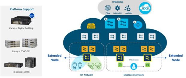
Many organizations are adopting Internet of Things devices and connecting them to the Cisco Industrial Ethernet switches or Cisco Digital Building switches. These switches do not support the SGT enforcement or VXLAN encapsulation required to be an edge node within SD-Access. Organizations want to be able to automate the configuration of these devices and gain the benefits of the security and policy that the fabric brings. To solve this problem, Cisco introduced the extended node feature.

Figure 3: Extended Node Overview — Courtesy of Cisco
The extended node connects directly to your fabric edge via a single 802.1Q trunk port. For wired devices, the switch ports are statically assigned to IP pools, or virtual local area networks (VLANs). SGT tags are then statically mapped to these IP pools within DNA Center. This means that the client gets the proper macrosegmentation (virtual routing and forwarding) and microsegmentation (SGT) applied.
It’s worth driving home the point that this mapping is static, where normally hosts are onboarded dynamically with 802.1X (which is not supported).
Security Group Access Control List (SGACL) enforcement is applied at the fabric edge node, as the extended nodes do not support SGT-based enforcement. That means, on a given extended node switch, you cannot enforce east-west traffic. This solution is ideal for securing north-south flows.
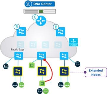
You can also connect a fabric-enabled access point (AP) to an extended node. In this scenario, it will simply see the extended node as an underlay device (intermediate node) and establish a one hop VXLAN tunnel to the edge node. The fabric-enabled AP will function as if it was connected directly to the fabric edge.

Figure 4: Extended Node Example — Courtesy of Cisco
Note: This feature is in beta in v.1.2 with some major caveats. CDW does not recommend running beta features in production.
Enhanced Host Onboarding
In SD-Access, host onboarding is defined as authenticating the user/endpoint and assigning them to the proper virtual network and IP Pool and applying the correct SGT. To do this, there is authentication, authorization and accounting configuration applied to the network-access device, which is a switch or wireless LAN controller for SD-Access.
Prior to SD-Access v.1.2, this configuration was predefined and not user modifiable. We found that many customers needed the ability to modify things like authentication order, timeout periods and so on.
With SD-Access v.1.2, Cisco added Auth-Template customization, which allows you to customize all the above items and more. It also added support to point to a virtual IP address (VIP) for customers who have Identity Services Engine Policy Service Nodes behind a VIP address in a data center, a very common deployment type.
Learn more about CDW’s network infrastructure solutions and services.
